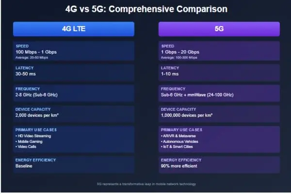
4G and 5G Comparison
Unlike 4G, which primarily used mid-band spectrum, 5G employs a three-tier spectrum strategy:
Low-Band (Sub-1 GHz):
- Frequencies: 600-900 MHz
- Coverage: Up to 10kilometresrs per tower
- Speed: 50-250 Mbps
- Use case: Wide-area coverage, rural deployment
- Characteristics: Similar coverage to 4G but with G’s architectural improvements
Mid-Band (1-6 GHz, especially C-Band at 3.5-4.2 GHz):
- Coverage: 1-kilometresrs per tower
- Speed: 100-900 Mbps
- Use case: Urban and suburban deployment, the “eet sp”t” for 5G
- Characteristics: Balances coverage and capacity
High-Band (mmWave, 24-100 GHz):
- Coverage: 100-300 meters per small cell
- Speed: 1-10+ Gbps
- Use case: Dense urban areas, stadiums, airports
- Characteristics: Extreme capacity but requires very dense deployment
This multi-band approach allows operators to use the right spectrum for the right situation, deploying low-band for coverage, mid-band for capacity, and high-band for extreme performance in concentrated areas.
5G Performance Characteristics
Speed:
- Theoretical peak: Up to 20 Gbps
- Typical real-world (mid-band): 100-900 Mbps
- Typical real-world (mmWave): 1-4 Gbps
Latency:
- Average (eMBB): 10-20 milliseconds
- Ultra-low (uRLLC): 1-5 milliseconds
- Theoretical minimum: Under 1 millisecond
Capacity:
- Device density: Up to 1 million devices per square kilometre
- Spectral efficiency: Up to 3x better than 4G
Energy Efficiency:
- Approximately 90% more energy efficient per bit of data transmitted compared to 4G
- Critical for supporting billions of battery-powered IoT devices
Part 4: Comprehensive 4G vs. 5G Comparison
Architecture Comparison
4G Architecture:
- Hardware-centric design with fixed network elements
- Evolved Packet Core (EPC) with separate entities (MME, S-GW, P-GW)
- Centralised processing at the core network
- Limited flexibility for new services
- Single network serves all use cases
5G Architecture:
- Software-centric, cloud-native design
- Service-Based Architecture (SBA) with modular network functions
- Distributed processing (edge computing capabilities)
- Highly flexible, programmable network
- Network slicing allows multiple specialised virtual networks
Radio Technology Comparison
4G Radio:
- OFDMA for downlink (tower to device)
- SC-FDMA for uplink (device to tower)
- MIMO with up to 8 antennas
- Primarily mid-band spectrum (under 6 GHz)
- Fixed beam patterns
5G Radio:
- CP-OFDM (Cyclic Prefix OFDM) for both downlink and uplink
- Flexible numerology (variable subcarrier spacing)
- Massive MIMO with 64-256 antennas
- Three-tier spectrum approach (low, mid, high/mmWave)
- Dynamic beamforming and beam tracking
Coverage and Deployment
4G Coverage:
- Single tower covers 1-5kilometresrs, depending on frequency
- Macro cell architecture
- Relatively simple deployment
- Good building penetration on all bands
5G Coverage:
- Low-band: Similar to 4G (wide coverage)
- Mid-band: 1-kilometresrs per site
- mmWave: 100-300 meters per small cell
- Heterogeneous network (HetNet) mixing macro cells and small cells
- More complex deployment, especially for mmWave
- mmWave requires line-of-sight or near-line-of-sight
Latency Deep Dive
Latency consists of several components:
4G Latency Breakdown:
- Radio interface: 10-20 ms
- Core network processing: 10-30 ms
- Transport delays: 5-20 ms
- Total: 30-70 ms typical
5G Latency Breakdown:
- Radio interface: 1-5 ms (shorter frame structures)
- Core network processing: 2-5 ms (edge computing)
- Transport delays: 1-5 ms
- Total: 5-15 ms typical, under 1 ms possible for uRLLC
The dramatic latency reduction comes from multiple improvements:
- Shorter Transmission Time Intervals (TTI)
- Edge computing (processing data closer to users)
- Optimised protocol stack
- More efficient scheduling
Spectrum Efficiency
Spectrum efficiency measures how much data can be transmitted per unit of spectrum bandwidth.
4G Spectrum Efficiency:
- Downlink: Up to 15 bps/Hz (bits per second per Hertz)
- Uplink: Up to 6.75 bps/Hz
5G Spectrum Efficiency:
- Downlink: Up to 30 bps/Hz (2x improvement)
- Uplink: Up to 15 bps/Hz (2.2x improvement)
This doubling of efficiency means that even using the same amount of spectrum, 5G can deliver twice as much data as 4G.
Energy Efficiency
4G Energy Profile:
- Base stations consume significant power
- Limited sleep modes for devices
- Energy per bit: baseline reference
5G Energy Profile:
- 90% reduction in energy per bit transmitted
- Enhanced sleep modes for IoT devices
- Network functions can scale power based on demand
- More efficient signal processing
This efficiency is crucial for IoT deployments where sensors need to operate on battery power for 5-10 years.
Security Enhancements
4G Security:
- Basic encryption (128-bit)
- Authentication based on SIM cards
- Vulnerable to certain types of attacks (IMSI catchers)
5G Security:
- Enhanced encryption (256-bit)
- Improved authentication protocols
- Concealed identifiers (protection against IMSI catchers)
- Better protection against man-in-the-middle attacks
- Network slicing provides isolation between services
- Zero-trust security architecture
Device Complexity
4G Devices:
- 2-4 antennas are typical
- Support for 2-3 frequency bands is common
- Moderate baseband processing requirements
- Matureoptimiseded chipsets
5G Devices:
- 4-8 antennas or more
- Must support multiple bands (low, mid, possibly mmWave)
- Significantly higher processing requirements
- More complex RF (radio frequency) design
- Higher power consumption (especially mmWave)
- More expensive to manufacture initially
Part 5: Real-World Applications and Use Cases
4G Applications: What It Enabled
4G made several revolutionary applications practical:
Mobile Video: Netflix, YouTube, and other streaming services became viable on mobile devices, fundamentally changing media consumption.
Ride-Sharing: Uber and Lyft rely on G’ss’s reliable data connections for real-time location tracking, routing, and payment.
Mobile Cloud Services: Dropbox, Google Drive, and iCloud became practical for mobile users.
Social Media: Instagram, Snapchat, SnapchatToandd video-centric experiences require 4G speeds.
Mobile Payments: Apple Pay, Google Pay, and similar services depend on reliable mobile connectivity.
5G Applications: New Possibilities G’s G’s
5 Gs’ enhanced capabilities enable entirely new categories of applications:
Autonomous Vehicles:
Self-driving cars need to communicate with each other (V2V – Vehicle to Vehicle) and with road infrastructure (V2I – Vehicle to Infrastructure) with extremely low latency. G’s sub-10ms latency makes this possible.
A travelling at 60 travelling at 88 feet per second. Withfeets 50ms latencWithhiclecar travels over 4 feet before receiving a response. Receiving 5ms latency, that distance drops to less than 5 inches, the difference between a collision and a near-miss.
Remote Surgery:
Surgeons can control robotic surgical instruments from thousands of miles away, but only if the latency is low enough that their hand movements translate instantaneously to the robot. Gs’s URLLC mode makes this feasible, with latencies under 10ms and reliability of 99.999%.
Industrial IoT and Smart Factories:
Modern factories use thousands of sensors and actuators that must coordinate in real-time. 5 G’s massive device density (1 million devices per square kilometre) and network slicing allow dedicated, reliable connections for critical manufacturing equipment while simultaneously supporting worker devices and monitoring sensors.
Augmented Reality (AR) and Virtual Reality (VR):
Authentic AR glasses that overlay digital information on the real world require massive bandwidth and minimal latency. Current AR devices are limited because processing happens on the device itself. Enables “split rendering” where complex graphics processing occurs in edge data centres and streams to lightweight glasses, making all-day AR glasses practical.
Smart Cities:
Cities can deploy millions of sensors for traffic management, air quality monitoring, waste management, parking, street lighting, and public safety. G’ss mMTC mode supports this massive connectivity with efficient battery usage.
Tactile Internet:
The ultimate 5G application, transmitting the sense of touch over networks. With the sub-5ms latency, you could feel texture, resistance, and feedback from remote objects, enabling applications like remote equipment maintenance, training simulations, and telepresence robotics.
Technology Solutions Professional: Guide + 5 Key Responsibilities
Part 6: Deployment Challenges and Realities
4G Deployment: Lessons Learned
4G deployment was relatively straightforward compared to 5G:
Infrastructure:
- Upgraded existing cell towers with new equipment
- Moderate backhaul requirements (fibre or microwave)
- Gradual rollout over several years
- Clear coverage footprint per tower
Challenges:
- Spectrum acquisition costs
- Backhaul capacity constraints
- Device fragmentation across frequency bands
- Voice over LTE (VoLTE) required network upgrades
5G Deployment: Complex Reality
5G deployment presents unprecedented challenges:
Infrastructure Requirements:
Fibre Backhaul: 5G, especially mmWave, requires vastly more backhaul capacity. Ch small cell might need 10+ Gbps fibre connections. The infrastructure often doesn’t exist and is expensive to deploy.
Small Cell Density: mmWave deployment requires small cells every 100-300 meters in urban areas. This means thousands or tens of thousands of installations in a single city.
Power and Site Acquisition: Each small cell needs power and site rental agreements. OrOrdainingousands of installations with property owners, municipalities, and utilities is logistically complex.
Spectrum Complexity:
Unlike 4G, where most deployments used similar frequency bands globally, 5G involves:
- Different countries allocate different frequency bands
- Devices must support many more band combinations
- Operators must coordinate deployment across low, mid, and high bands
- Spectrum auctions costing billions of dollars
The mmWave Reality Check:
Initial 5G marketing focused heavily on mmWave’s multi-gigabit speeds, but the deployment reality has been sobering:
- mmWave coverage is minimal
- Building penetration is negligible.
- Weather impacts performance
- Cost per covered area is 10-100x higher than mid-band
- User experience is inconsistent (works great outdoors in dense cities, poorly elsewhere)
Most 5G deployments now focus on mid-band (especially C-Band) as the primary performance layer, with low-band for coverage and selective mmWave in very high-traffic areas.
The “Nationwide 5G” Controversy
Many carriers advertised “nationwide 5G” coverage, but the reality was often low-band 5G that offered speeds only marginally better than 4G. There is an excellent deal ofconsumer confusion and disappointment.
Actual 5G performance advantages require mid-band or mmWave deployment, which covers far less area and remains unavailable in many regions.
Part 7: Technical Deep Dives
Understanding OFDM and Numerology
Both 4G and 5G use variations of OFDM (Orthogonal Frequency-Division Multiplexing), but 5G introduces “flexible numerology” that 4G lacks.
Basic OFDM Concept:
Instead of using one wide frequency channel to transmit data, OFDM divides the spectrum into many narrow subcarriers. Think of it like dividing a wide river into many narrow channels—if one channel encounters an obstacle (interference), the others continue flowing.
Subcarrier Spacing:
4G LTE uses fixed 15 kHz subcarrier spacing. Each subrier is 15,000 Hz wide, regardless of the application.
5G introduces flexible numerology with subcarrier spacings of 15, 30, 60, 120, or even 240 kHz. T is flexibility allows optimisation:
- Narrow spacing (15 kHz): Better for coverage and long-range
- Wide spacing (120-240 kHz): Lower latency for time-critical applications
- Variable spacing allows different slices to use different configurations
Why This Matters:
Wider subcarrier spacing means shorter symbol duration, which reduces latency. A 120 kHz carrier spacing cuts latency by 75% compared to 15 kHz spacing. However, wider spacing is more sensitive to Doppler shift (frequency changes caused by movement), so it’s best for stationary or slow-moving devices.
Understanding Modulation: How Data Becomes Radio Waves
Modulation is the process of encoding digital data (ones and zeros) onto radio waves for transmission.
Amplitude Modulation (AM):
- Varies the signal strength (amplitude)
- Simple but inefficient
- Susceptible to noise
Phase Modulation (PM):
- Varies the timing (phase) of the wave
- More resilient to noise
- Can encode more data per symbol
Quadrature Amplitude Modulation (QAM):
- Combines both amplitude and phase modulation
- Used by both 4G and 5G
- Higher-order QAM packs more data per symbol
4G Modulation:
- Up to 64-QAM (6 bits per symbol) standard
- 256-QAM (8 bits per symbol) in LTE-Advanced
5G Modulation:
- Up to 256-QAM (8 bits per symbol) standard
- Potential for 1024-QAM (10 bits per symbol)
Higher-order modulation allows more data transmission but requires cleaner signals with less interference. T is y 5 G’s beamforming is crucial, it creates cleaner signal paths that can support advanced modulation.
Understanding Duplexing: Two-Way Communication
Radio communication requires both transmitting and receiving. There are two main approaches:
Frequency Division Duplexing (FDD):
- Uses separate frequency bands for uplink (device to tower) and downlink (tower to device)
- Both directions can operate simultaneously
- Requires paired spectrum (two separate bands)
- Used by most 4G LTE deployments
Time Division Duplexing (TDD):
- Uses the same frequency band for both directions
- Alternates between uplink and downlink in time slots
- Requires only an unpaired spectrum (one band)
- More flexible allocation of uplink/downlink capacity
- Preferred for 5G, especially mid-band and mmWave
TDD’s flexibility is essential because internet usage is asymmetric; we download far more than we upload. TDcan locate 80% of time slots to downlink and 20% to uplink, matching actual usage patterns. F D must splitthe spectrum 50/50 regardless of usage.
Edge Computing: Bringing Processing Closer
One of 5 G’ss architectural innovations is native support for edge computing (also called Multi-access Edge Computing or MEC).
Traditional Cloud Model:
- Your device sends data to a distant data centre (possibly hundreds or thousands of miles away)
- Processing occurs
- Results return to your device
This round trip adds latency—typically 50-100ms or more.
5G Edge Computing Model:
- Your device sends data to a local edge server (possibly in the cell tower building itself)
- Processing occurs locally
- Results return in 5-10ms
This architecture is crucial for latency-sensitive applications. F r exam e:
- Autonomous vehicles can’t wait 50ms for cloud processing of sensor data
- VR/AR applications need instant rendering to prevent motion sickness
- Industrial robots require an immediate response to sensor inputs
5 G’ss architecture includes the User Plane Function (UPF) that can be deployed at the network edge, processing and routing data locally without sending it to the core network.
Beamforming Technical Details
Let’s explore how beamforming actually works:
Antenna Arrays:
A massive MIMO base station has 64-256 antenna elements arranged in a grid. Each antenna can transmit the same signal with slight timing differences.
Constructive and Destructive Interference:
When radio waves from multiple antennas arrive at the same point, they interfere with each other. If the waves arrive “in phase” (peaks aligned with peaks), they add together (constructive interference). If they come “out of phase” (peaks aligned with troughs), they cancel out (destructive interference).
Creating a Beam:
By precisely controlling the timing and phase of signals from each antenna, the base station can ensure constructive interference in one specific direction (creating an intense beam) while causing destructive interference in other directions (minimising signal elsewhere).
Think of it like ripples in a pond from multiple stones. If you drop the rocks at precisely the correct times and positions, the ripples can align to create an intense wave moving in one direction while cancellingout in other directions.
Beam Tracking:
Your device continuously sends feedback about signal quality. The base station uses this feedback to adjust its beam direction in real-time, tracking your device as you move. This processhappens any timeper second, creating the illusion of a “laser pointer” that follows you.